
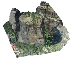
Generation of high-resolution 3D models: The vertical and oblique aerial images as well as the terrestrial images were oriented through the Structure from Motion (SfM) technique and a sparse 3D point cloud was generated. The SfM method simultaneously determines the camera poses, i.e., the camera exterior orientation parameters and optionally the camera interior orientation, and sparse 3D point clouds. The camera poses and the object geometry are determined by automatically locating homologous feature points (tie points) in overlapping images. The SIFT algorithm or its variants are mainly used for feature extraction and description. For each feature point, a descriptor vector is calculated based on its “neighborhood”. A RANSAC-based algorithm is generally used to identify and eliminate erroneous matches and improve the success rate of the SfM method. Large overlaps among the images are generally required for the successful implementation of SfM. In the context of the METEORA project, GCPs were measured in the field for the scope of georeferencing the SfM results. The Agisoft Metashape software as well as the RealityCapture software were used for comparative evaluation of the results. Then, dense point clouds were computed through a dense image matching process. For the implementation of dense image matching, computer vision algorithms (e.g., semi-global matching) are used to calculate the 3D object coordinates for each pixel, and not only the coordinates of the feature points. This process results in very dense point clouds, covering all parts of the object depicted in at least three images. During the last stage of the 3D modeling process, the 3D model of the scene is produced as a continuous surface, in the form of triangles (TIN) or other more advanced forms (curves, nurbs). The 3D surface model can be further enriched with texture mapping, thus including the maximum possible information. The creation of 3D surface models for the Archaeological Site of Meteora as well as the Modi and Alyssos rocks was implemented using the Geomagic Studio software.
Photogrammetric processing of LiDAR data and aerial images taken by the system RIEGL VQ-1560i-DW: As far as the processing of aerial images is concerned, the RAW RGB images were initially converted to .tif images. Then, the Phase One IXU 1000RS camera parameters were imported into the Erdas Imagine Professional software and tie points were automatically generated, as required for the aerial triangulation process. The processing of LiDAR data includes the conversion of LiDAR cloud points into the .las format and the organization of data in blocks of 500m × 500m so that they can be easily processed. Two procedures were applied for strip alignment through the Terrasolid Terrascan software:
- 1st application: strip alignment per scanner
- 2nd application: strip alignment per flight line